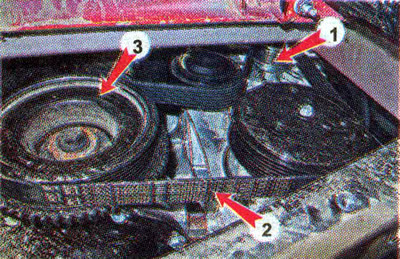
The car is equipped with a three-phase alternator with electromagnetic excitation, a diode rectifier unit and a built-in voltage regulator.
The drive of the generator 1 is carried out by the V-ribbed belt of the drive of auxiliary units 2 from the crankshaft pulley 3.

The generator consists of a rotor, a stator, a rectifier unit, a brush assembly with a voltage regulator and two covers. A pulley is installed on the rotor shaft. To cool the parts of the generator, ventilation holes are made in its covers, and an impeller is made on the rotor from the side of the front cover.
The stator has a three-phase winding connected «star». The winding leads are soldered to the rectifier unit. The rectifier unit is installed under the generator casing together with the brush assembly and voltage regulator.
The rotor has an excitation winding, the leads of which are soldered to two contact rings.
The generator rotor shaft rotates on two ball bearings. The front bearing is pressed into the front cover of the generator, and the rear bearing is pressed onto the rotor shaft and held on the rear cover of the generator.
The voltage regulator is non-contact, electronic, combined with a brush assembly in a common non-separable housing. The voltage regulator is controlled by the electronic engine control unit (ECU). Brushes - carbon, spring-loaded.
Comment. The alternator is a difficult to dismantle structure, therefore, in the event of a malfunction, it is recommended to contact a specialized workshop or replace the complete alternator. This Chapter describes only those operations, the implementation of which does not require special skills and equipment.
Recommendation. If the battery indicator light on the instrument panel lights up, do not rush to immediately remove the generator for repair or replacement. First make sure that the problem is caused by a failure of the generator itself, and not by the wires of its electrical circuit or by loosening the drive belt (see below, «Diagnostics of malfunctions of the generator»).
